Thread : http://electro-music.com/forum/topic-38321.html
BOM : https://docs.google.com/spreadsheets/d/1oC8qTPuI9R7RBQtbB2iEcsH-pSuk7au4df7enVTY9tk/edit?usp=sharing
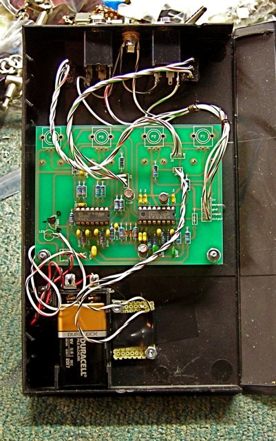
I noticed a small error on the schematic diagram. It has C9 - pin 9 on the delay chip - as 9100nF. Looking at the overlay and photo here it appears that the extra 9 is a typo, it should probably be 100nF. http://electro-music.com/forum/post-356382.html#356382
can i use 7805? > yes, it's just a 5v line for the delay chip. 7805 work fine. http://electro-music.com/forum/post-356623.html#356623
From Left to Right ( P4, P3, P2, P1 )
Input Level, Wet/Dry mix, Modulation Depth ( from external CV ), Delay Time.
The CV input is to control the delay time? > Yes
What is SENSOR doing?(HDR 10) > It is an LDR, presumably to control delay time according to light level.
What are the functions of JUMPER and the two HDR 3? jumpers for a different settings ? > HDR_3 allows you to bypass the external CV option the jumper allows you to bypass the LDR if you don't want to use it.
The JUMPER next to the led says + and -, should I consider - as Ground?? > Yes -Ve appears to be ground in this circuit. As it works from a single supply. http://electro-music.com/forum/post-428333.html#428333
One switch will switch the audio output to the point right before the delayline or right after the delayline. The other switch will switch between the LDR (or any other resistive) sensor or the delaytime modulation CV input on the 2×5 header. http://electro-music.com/forum/post-271963.html#271963
The Zeitgeist has a +5V regulator that accepts a power supply voltage of +6V to +20V. The Zeitgeist uses roughly between 20mA and 40mA of current, depending on the delaytime. http://electro-music.com/forum/post-271977.html#271977
The output switch selects between “delayed signal” and “delayed signal + input signal”. Is that correct?> Yes, it switches the output 'pre-delayline' or 'post-delayline'.
For the LDR it looks like there are two places on the board where it can be connected: one on the “sensor” input on the 10 pin header and one on the two prong header by the switch to select CV or LDR (for control of the delay time). Is that correct? > It should best be connected to the two prong header. http://electro-music.com/forum/post-272072.html#272072
It is a green LED, but it's burning yellow is caused by too much current passing. So eventually it burns through, as did mine as well. I just removed and bypassed it. That works and is safe as there is a voltage regulator after the LED. Another option is to remove the LED and insert a switch there for power on-off. http://electro-music.com/forum/post-301256.html#301256
For the Op Amp IC, I used an LM 324 per Rob's recomendation. http://electro-music.com/forum/post-274537.html#274537
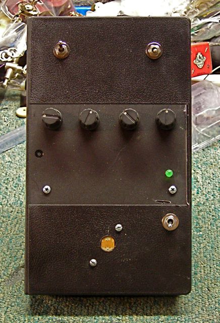
Switches names suggestion
Output : “Pre” “Post” Modulation : “CV” “Sensor”